TM 55-203
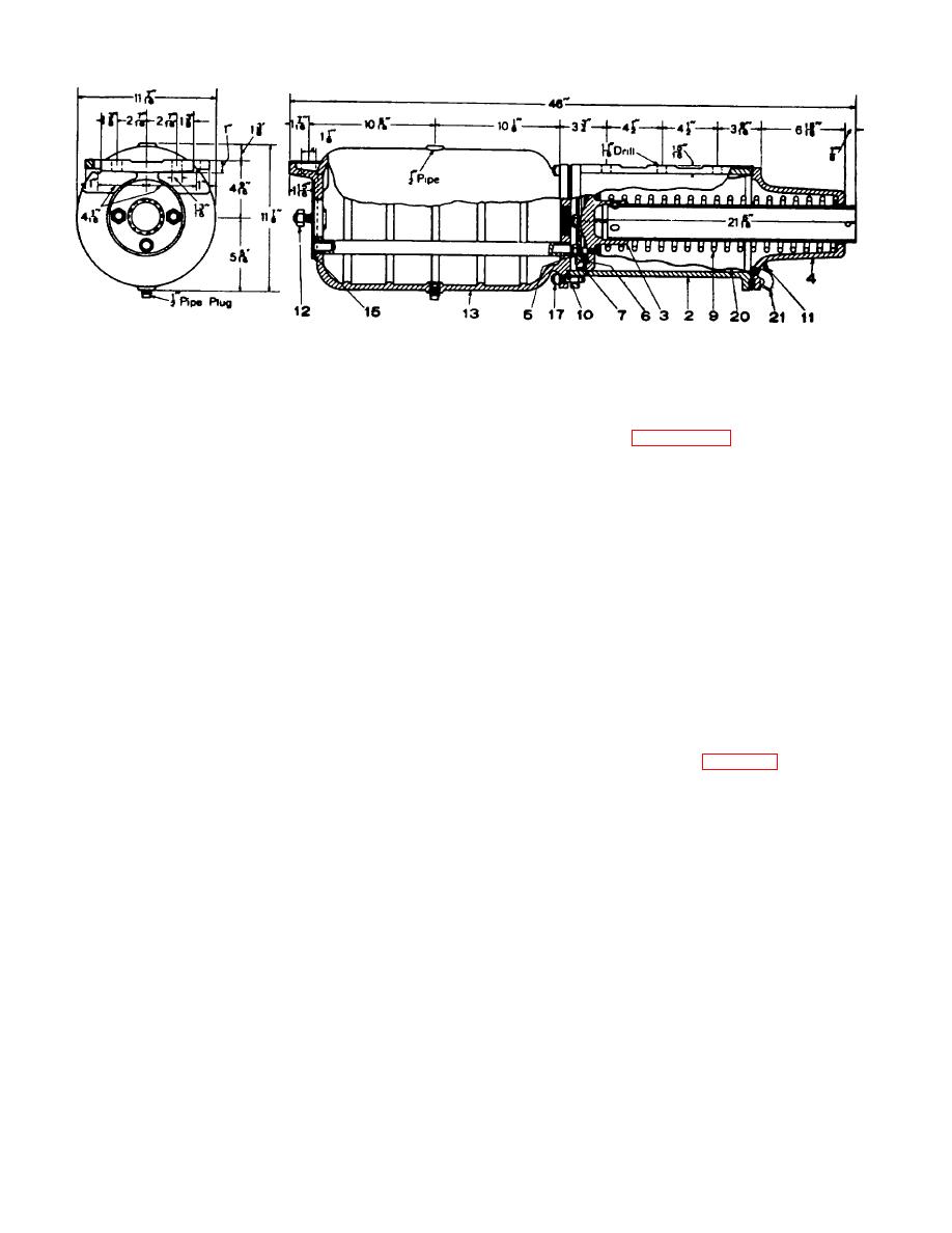
Figure 8-34. Sectional and end view 8 -by 12-inch freight brake cylinder and reservoir combined.
restricted so that release of the brake is slower than in
(5) Brake cylinder pressures. Spring 21 is
low pressure position.
capable of retaining a pressure of 10 pounds in the
g. Vent Protector and Improved Wasp Excluder for
brake cylinder. As long as the pressure of the air from
the brake cylinder is greater than this, valve 5 is
unseated and the air exhausts to the atmosphere
retaining valve with a vent protector (26) and an
through the vent port which, being ,small, makes the
improved wasp excluder (23). The vent protector is
release of the brake much slower than when the
molded Wabco and fits tightly over the low pressure
retaining valve is not used. When the pressure has
capnut to protect the small vent port against the
been reduced to 10 pounds, it is no longer able to hold
entrance of moisture which may cause corrosion and
valve 5 off its seat and the valve then closes and the
consequent restriction or stoppage of the port. The
remaining 10 pounds is retained in the brake cylinder
improved wasp excluder contains a flexible Wabco disc
until the handle 5 is turned down. Failure of the
which normally maintains a seal against the entrance of
pressure retaining valve to hold air in the brake cylinder
water and wasps, but flexes readily to permit free
generally is due to a leak in the connecting pipe, a
exhaust of brake cylinder air through the retaining valve
frequent seat of trouble being at the union; it may also
exhaust. The excluder is applied to the tapped exhaust
be due to a leak in the brake cylinders or in the retaining
opening by a hollow capscrew, having a cross port
valve, but seldom in the latter. When it is desired to
through which air passes to the excluder exhaust. Both
retain high pressure in the cylinder, the handle is placed
the vent protector and the wasp excluder are applicable
in the intermediate position marked HP. In this position,
to retaining valves in service.
passage a connects chamber D with port d so that the
h. Four-Position Release Control Retainer
air pressure must lift valve 4 against the 10-pound value
(1) Features.
The four-position type of
of spring 20. The air then 'passes through choke g to
release control retainer (fig 8-40), accepted as a
valve 5, which will be lifted from its seat against the 10-
recommended practice by the AAR and acceptable on
pound value of its spring 21, resulting in a pressure of
cars in interchange service in CONUS has the same
10 pounds in the spring chamber over valve 4. With 10
features of the AAR standard retaining valve, plus a
pounds air pressure plus 10 pounds spring pressure
fourth position which affords a slowdown release of
acting above valve 4, pressure of 20 pounds is required
brake cylinder pressure from 50 pounds to 10 pounds in
to unseat this valve. Consequently, 20 pounds air
approximately 86 seconds.
The purpose of this
pressure will be retained in the brake cylinder. The air
additional position is to provide a better control of slack
which is vented to atmosphere in this position passes
in long freight trains during release of the brakes while
valve 4, through choke k, valve 5 and through choke h.
the train is in motion, especially in cases where trains
In passing through both chokes k and h, the flow of air is
are operated over rolling country.
The use
8-42


 Previous Page
