TM 55-203
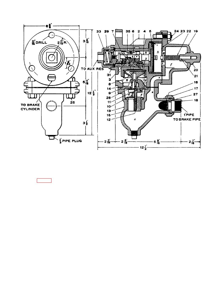
Figure 8-32. K-2 triple valve, actual section and end view
strains are removed from its weakest point and
permits longer time between cleaning periods (may be
concentrated at its strongest point. The gasket is under
the same as for triple valve and brake cylinder).
an initial strain, but it is not subject to any subsequent
movement because the union flange is drawn up solid,
(2) Check valve. The purpose of the check
metal to metal (fig 8-36).
valve is to hold in the dirt chamber the collected dirt
under all conditions of airbrake operation. The body
e. Centrifugal Dirt Collector
portion has a machined seat against which the check
valve seats when a heavy reduction in pressure occurs
above it, such as that during an emergency application,
(1) Location. The centrifugal dirt collector is
thereby shutting off communication between the dirt
located in the branch pipe in order to protect the triple
chamber and the dirt collector outlet. The check valve
valve against the entrance of pipe scale, sand, cinders,
is so designed and placed on the valve stem as to
dirt, or foreign substances of any kind. Figure 837 is a
permit a rocking motion whereby any fine dust which
sectional view of the standard "Check Valve Type" in
may collect on top of the check valve will be shaken off
which the detachable enlarged dirt chamber and the
into the dirt chamber.
check valve are the outstanding features. This design
comprises two separate portions; the upper or body
f. Pressure Retaining Valve
portion to which the pipe connections are made, and the
lower or dirt chamber portion which contains the brass
umbrella-shaped check valve. The two portions are
(1) Description. The following description of
bolted together and the joint between is protected by
the pressure retaining valve applies in detail
means of a rubber gasket. The detachable dirt chamber
provides for easier cleaning, and the increased capacity
8-40


 Previous Page
