TM 55-203
to the AAR standard. Many older types are in service
which differ in detail, but the principle of operation is the
same and that portion of the text covering operations,
therefore, applies to the older as well as the newer types.
(2) Standard retaining valve.
The standard
retaining valve for freight equipment cars is a three-
position, 10to 20-pound duplex spring type retaining valve
having nominal blowdown valve of 50 seconds in the 10-
pound position and 90 seconds in the 20-pound position. A
wasp excluder fitting (g below) is provided in the exhaust
opening to prevent the plugging of the exhaust by the
entrance and nesting of mud wasps and other insects A
fixed choke orifice (choke k) is incorporated in the passage
(port g) between the high and low pressure cavities, and
the springs and valves are permanently enclosed in the
capnuts, thereby preventing possibility of spring distortion
and assuring permanent closing valves. Both chokes k
and h are drilled brass plugs and the choke ports are coned
on the pressure side to prevent dirt from accumulating and
closing the port.
(3) Adjusting the retaining valve. This valve is
connected to the triple valve exhaust as illustrated in figure
cylinder to exhaust freely to the atmosphere, or (b) to retain
a portion of the air in the brake cylinder when making a
release, in order to hold the brake applied while recharging
the system. The retaining valve is usually fastened to the
end of the car, near the brake staff, by lag screws or bolts.
(4) Lock key. The cock key, figure 8-38, has
three outlets: one to the atmosphere through the pipe tap
EXHAUST, one to the low pressure side of the retaining
valve proper and another to the high pressure side. The
valve portion consists of two valves 4 and 5 normally held
to their seats by their springs 20 and 21 and holding ports d
and e closed. When the handle of the retaining valve is
turned down, passage a in the cock key connects chamber
D and the outlet c to the atmosphere. When the handle is
turned up to the horizontal position, passage a connects
chamber D below the cock key with port e, so that when a
release is made the air exhausting from the brake cylinder
flows to the retaining valve and through passage a and
passage e to the face of the valve 5 which it must lift
against the pressure of spring 21 in order to flow to the
atmosphere through the small vent port h in the low
pressure capnut.
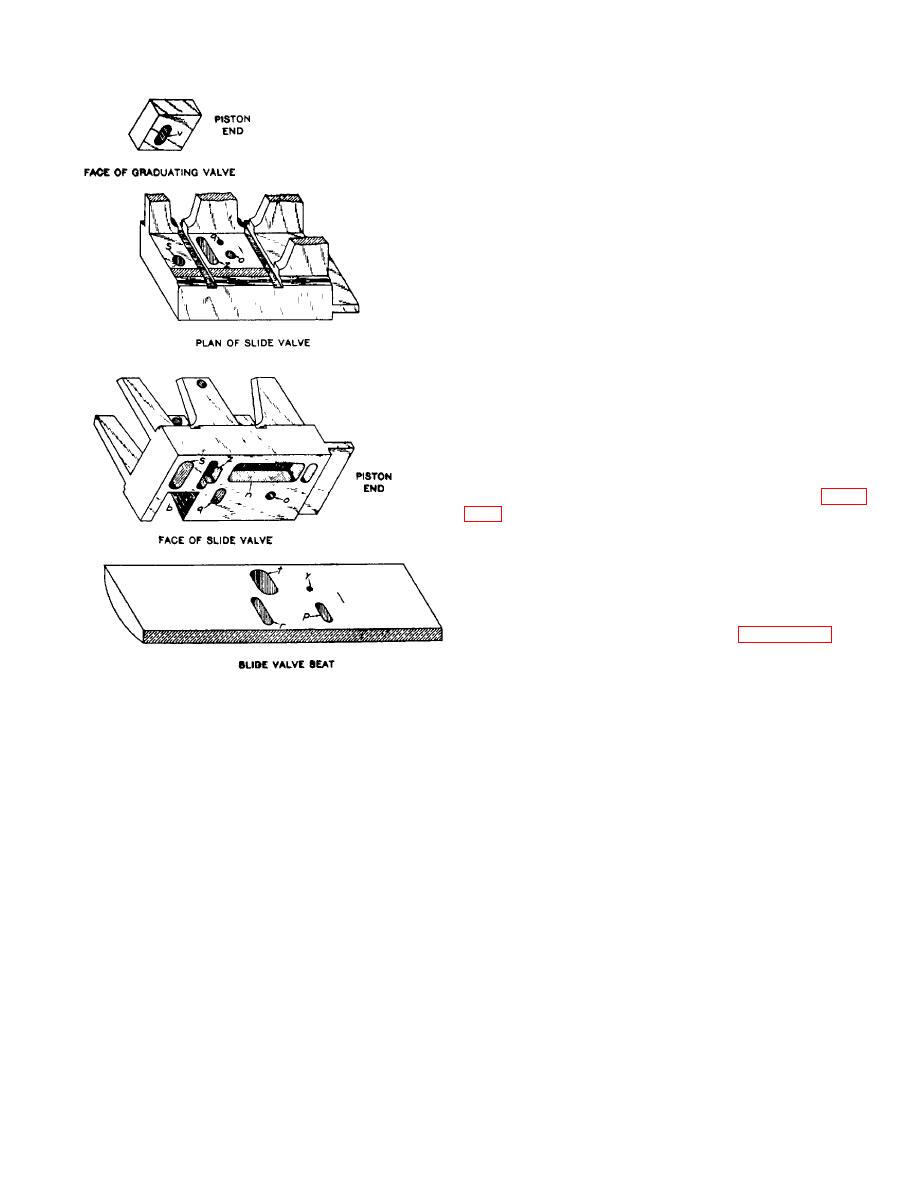
Figure 8-33. Isometric views of triple valve, slide valve
and seat, and the graduating valve.
8-41


 Previous Page
