TM 55-203
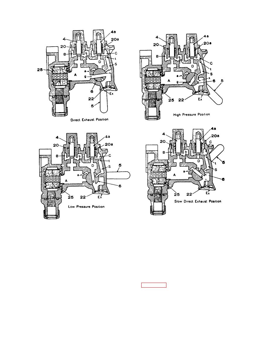
Figure 8-40. Diagrammatic views of four-position release control retainer.
the brake pipe to the auxiliary reservoir, as described,
the higher pressure on the auxiliary reservoir side of the
until their pressures become equal, when the latter is
piston is able to overcome the friction of the piston 4
then, fully charged.
and its attached graduating valve 7 and move these
parts to the left until the shoulder on the end of the
piston stem strikes against the right-hand end of the
c. Quick-Service Position
slide valve 3. The latter is then moved to the left until
the piston strikes the graduating stem 21, which is held
(1) First action. A quick service application of
in place by the compression of graduating spring 22.
the brake is obtained by making a gradual reduction in
The parts of the valve are then in the position shown in
brake pipe pressure. As soon as the pressure in
chamber H has been sufficiently reduced below that in
the feed groove i, preventing air from feeding back into
chamber R on the other side of the triple valve piston,
the brake pipe from the auxiliary reservoir, and at the
same time the graduating valve opens the
8-46


 Previous Page
