TM 55-203
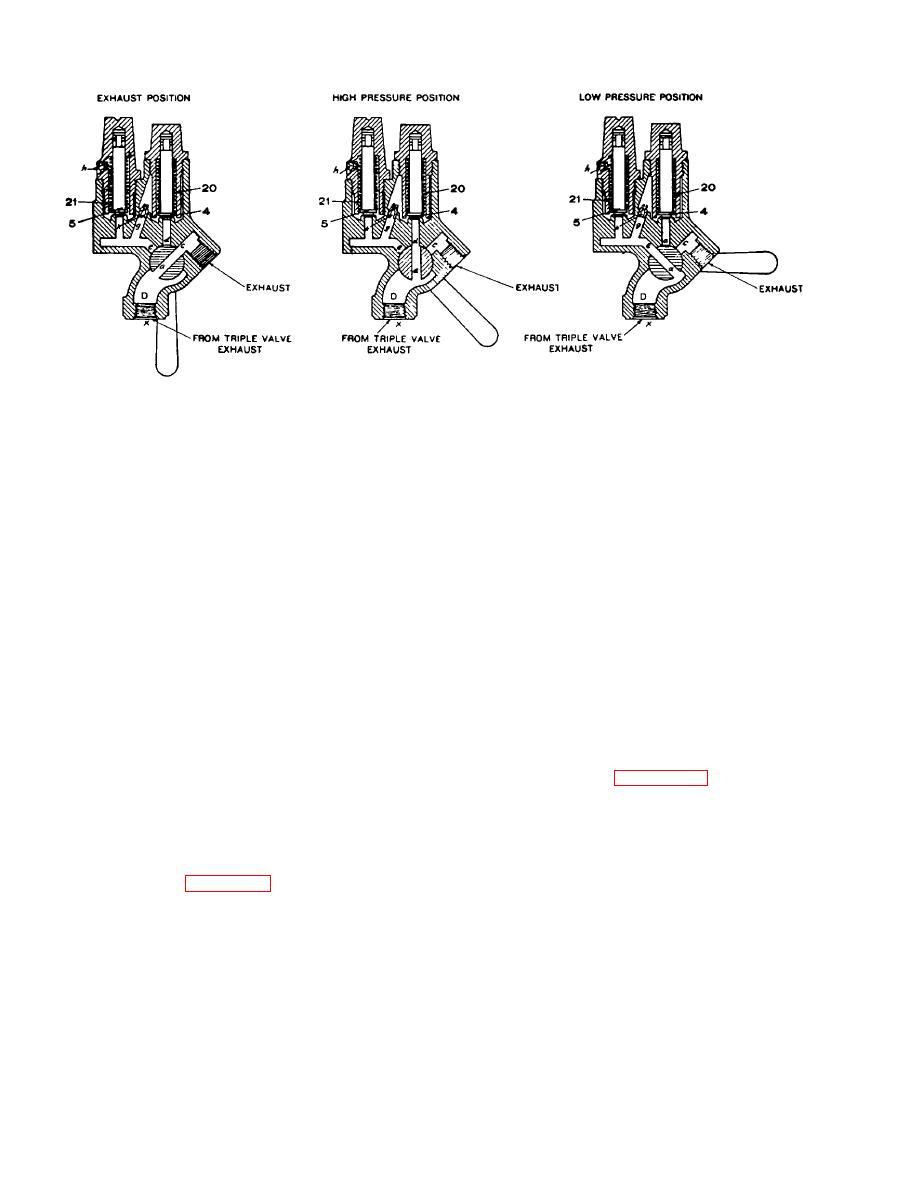
Figure 8-38. Diagrammatic views of standard pressure retaining valve.
parts are accessible for repair or replacement without
valves are in series, they will close and retain 20 pounds
removing the complete device from the reservoir. In
brake cylinder pressure. The blowdown time of the
order to inspect the valve assembly and spring, it is only
brake cylinder from 50 pounds to 20 through chokes b
necessary to remove the valve stem nut.
and t is approximately 90 seconds.
(2) Handle. The handle is made in two parts
(c) In low pressure position, handle 5 is turned to
which are pivoted to impart travel to the variable
the horizontal position marked LP. The triple valve
opening vent valve, thereby unseating the latter,
exhaust is through strainer 25, chamber A, past low
permitting the air to discharge from the reservoir. The
pressure valve 4, through choke b, chamber D, port g in
amount of travel of the variable opening vent valve
cock key 6, and past wasp excluder 22 to atmosphere
determines the rate of blowdown. A light or short pull on
Valve 4 will close to retain 10 pounds pressure in the
the hand rod results in a slow rate of discharge of
brake cylinder. The blowdown time of the cylinder from
auxiliary reservoir air, whereas a heavier pull, moving
50 pounds to 10 pounds through choke b is
the valve to its maximum open position, will cause
approximately 60 seconds.
auxiliary reservoir pressure to be exhausted from 70
pounds in approximately 3 seconds. This valve is
(d) In slow -direct exhaust position, handle 5 is
operated in the same manner as the old, by hand rods
turned to the position marked SD, 45 degrees above
from either side of the car, and being fitted with 1/2-inch
horizontal. The triple valve exhaust is through choke a,
pipe stud, is completely interchangeable with the old.
port g in cock key 6, and past wasp excluder 22 to
atmosphere. The blowdown time of the brake cylinder
from 50 pounds to 10 pounds is approximately 86
angle cock, one of which is installed at each end of the
seconds; however, brake cylinder exhaust continues
brake pipe as shown. The cock is open with the handle
until all pressure is vented.
parallel to the pipe line, as illustrated, and closed with
the handle crosswise or at right angles to the pipe line.
i. Variable Release Valve
The handle may be removed independent of the socket.
After driving out the hinge pin, the handle may be easily
removed by first depressing it and then sliding it forward
reservoir release valve which is of the variable reduction
to permit the web to clear the
type with a maximum rate of reduction that permits the
rapid depletion of auxiliary reservoir pressure. This
valve is installed horizontally, providing greater
clearance than the vertical type valve; and the internal
8-44


 Previous Page
