TM 55-203
of the airbrake system, thereby protecting the triple valve,
the use of the branch pipe tee will materially assist in
preventing the excessive deposit of moisture in the branch
pipe sometimes occasioned in charging and testing drains
from poorly designed yard plants, or because the
locomotive has insufficient reservoir capacity or cooling
pipe to insure precipitation of the water before passing to
the brake system. This fitting has the interior coring so
designed that the outlet from the brake pipe to the branch
pipe is at the top. Thus, as air enters at K from the brake
pipe it flows upward into chamber L and thence through the
pipe opening at the bottom to the branch pipe, the moisture
and heavy particles of dirt passing on through the brake
pipe.
which there is one, 1 1/4-inch size in the branch pipe,
should be placed where it can easily be reached but
protected from accidental closing. This cock, when closed,
cuts off communication between the brake pipe and the
triple valve. The handle should be in such a position that,
as affected by vibration, it would tend to jar open instead of
shut.
m.
the brake pipe continuous throughout the train. When cars
are being separated, as in switching, the angle cocks
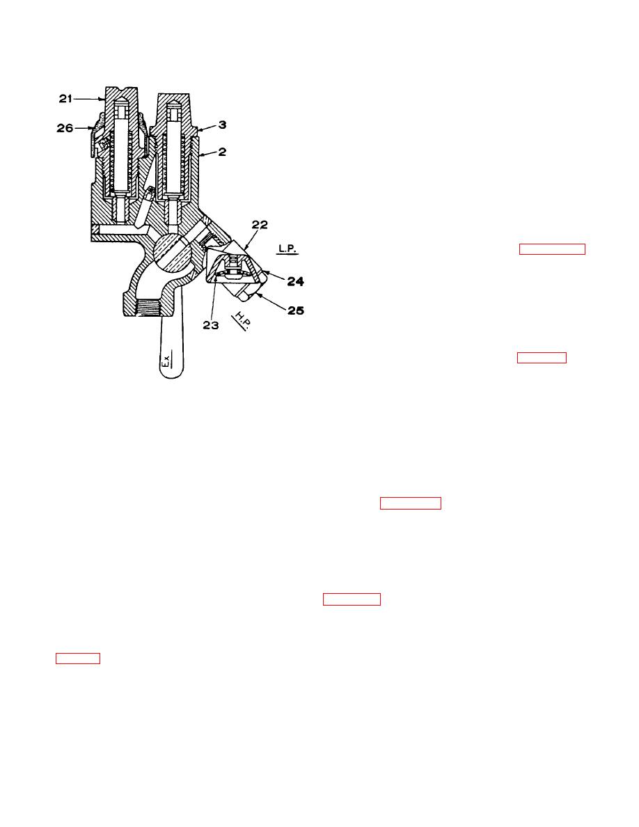
Figure 8-39. Sectional view of retaining valve with
should be closed and the hose should be uncoupled by
vent protector and improved wasp excluder.
hand, to prevent rupture or damage. Failure to uncouple
by hand causes shifting and breaking of the brake pipe as
socket lugs. The handle, of course, locks in both open and
well as damage to the coupling gasket and hose.
closed positions. When so locked, it is necessary to
slightly raise the handle before it can be turned, thus
8-23. Operation of Equipment
insuring against accidental opening or closing by being
a. General. As it is impossible to show all the ports
stepped upon, flying missiles, or loose rods and chains. An
and connecting passageways in the graduating valve, slide
extension with a U-bolt groove to the brake pipe end of the
valve, and seat by any single section taken through the
angle cock serves to support the brake pipe entering the
triple valve, figures 8-45 through 8-50 illustrate in a purely
angle cock while the groove in the extension permits the
diagrammatic way the relations of the various parts to each
angle cock to be positively attached to the hanger bracket.
other, for the different positions of the triple valve piston.
The hinge portion has been strengthened and the size of
The actual proportions and mechanical construction of the
the hinge pin increased to provide a larger bearing area. A
parts have been disregarded where necessary to make the
split type socket is used and the rivet pinhole for locking
connections 'and operation more easily understood.
the socket to the key is drilled through the split portion,
engaging a notched out cavity in the square of the key.
b. Full Release and Charging Position. As shown in
These changes provide greater strength and closer fit of
the hinge portion, and a close and permanent fit between
through passages a and e, cylinder cap ports f and g to
the 'handle socket and the cock key.
chamber H on the face of the triple valve piston; thence
through feed groove i, now open to chamber R above the
k Branch Pipe Tee. The purpose of the branch pipe
slide valve, which is always in free communication with the
tee (fig 8-42) is to prevent moisture that may be deposited
auxiliary reservoir. Air flows from
in the brake pipe, from any cause, draining into the branch
pipe connection and from thence into the triple valve.
While the centrifugal dirt collector has proved very efficient
in collecting moisture and dirt from the piping
8-45


 Previous Page
