TM 55-203
(3) Remove lock, lock lifter, and knuckle thrower.
(4) Remove cotter keys or bolts from draft key.
(5) Drift out the draft key from tapered end.
(6) Slide the coupler backward until two thirds out.
(7) Place a long bar or pipe immediately behind the
coupler head, under the thickest portion of the shank, and
with two men holding the bar or pipe in one hand, each
side, using the other hand to balance the coupler, lift it out
and lower to the ground.
(8) Remove yoke, draft gear, etc., as required (para 6-4b).
7-6. Couplers for Oversea Railway Equipment
With few exceptions, hook-and-link and Willison couplers
set at 41 inches coupler height predominate in oversea
areas. The exceptions are those areas such as Korea,
Japan, and China where AAR-type automatic couplers are
used. As stated previously, neither hook-and-link nor
Willison couplers transmit buff directly to the center sill
through draft gear. Buff loads are taken up by two side
buffers at coupler height above the top of the rail. Each
buffer is set approximately 35 inches off the longitudinal
centerline of the car. Design loads are fixed for both
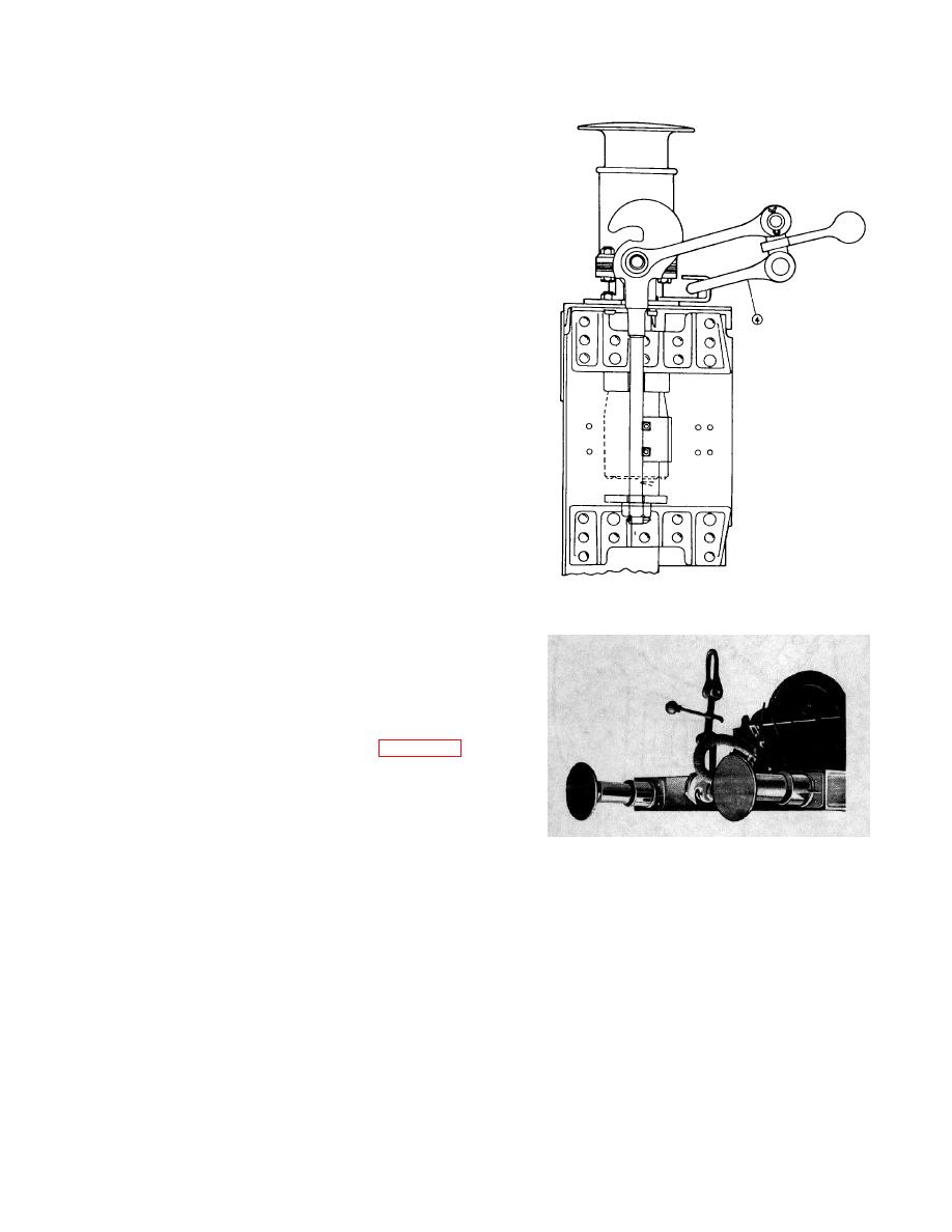
Figure 7-5. Hook and link (screw) coupler, buffer,
buffers and the hook and links of the coupler. This design
and draft gear.
establishes the maximum drawbar pull allowed when
fixing train tonnage' , and the useful life of the coupler is
s
directly related to the amount of misuse brought about by
overloading. One of the outstanding characteristics of the
hook-and link coupler is that its design provides for no
built-in slack between cars. Links are turned tight by
turnbuckles, thus losing all slack. These two coupling
devices are illustrated in figures 75 and 7-6. Figure 7-6
shows side buffer arrangement.
7-7. Hook-and-Link Couplers
a. General. The standard European coupler consists
of three main parts on each end of the car. These parts
Figure 7-6. Side buffers
are a screw coupling, a draw hook, and two buffer
of the clevis, screw and lever, and the shackle. Each
assemblies, illustrated in figure 7-. The draw hook forms
buffer assembly consists of a housing which is attached to
a part of the underframe of the car. The screw coupling is
the framework of the craft and in which is housed a
mounted at the base of the hook. The two buffer
spring-loaded section, extending out of the housing.
assemblies are located one on each side of the hook and
screw coupling toward the outer sides of the car, as
b. Operation. When cars are coupled, the shackle of
shown. The screw coupling consists
the screw coupling on one car is
7-4


 Previous Page
