TM 55-203
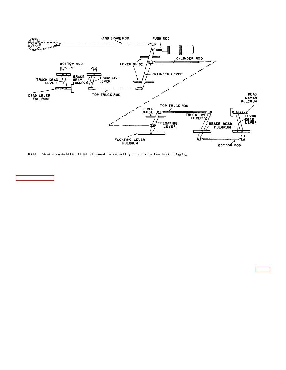
Figure 8-1. Foundation brake gear diagram.
engaging the notches. A single lever serves to take up
route in service. Maintenance is described in
slack on both trucks. To adjust piston travel: pull the
handle of the lever as far as it will go, then release. To
are described below.
release slack: push up pawl, then push back handle as
far as it will go.
b. Type 1. One type is provided with a notched
pull rod at each end of the car which is connected to the
d. Type 3. A third type is provided with a rotating
dead lever. To adjust piston travel: pull straight on the
square shaft, which is placed in a horizontal position
handle which is located on the right side of the coupler
under the car body, extending out under the outer sill of
and let go. A pawl on the notched pull rod locks when
the car. Two holes are drilled through the end of the
the rod is pulled as far as it will go. Then go to the
square shaft. A short bar can be inserted in the hole on
opposite end of the car and repeat the operation. To
any of the four sides. A pawl wheel is 'placed on the
release slack to change brakeshoes, pull handle, then
shaft, and the direction -to turn shaft to take up slack is
give it 1/8 turn to right, then push back all the way. This
indicated by an arrow on the housing inclosing the pawl
gives maximum slack in the brake.
wheel. To take up slack: insert a short bar in hole in end
of shaft, and turn shaft in direction indicated by arrow as
c. Type 2. Another type is provided with a rigging
far as it will go, then release. To release slack: release
lever which extends in a horizontal position to a point
pawl and turn shaft as far as it will go in opposite
near and just under the outer ledge of the car near the
direction. Adjustments for this type are shown in figure
center, or in some applications on hopper cars it is
8-4.
located at one end. The lever actuates a notched
square bar, which has a pawl underneath the bar,
8-2


 Previous Page
