TM 55-203
c. Knuckles. Excessive knuckle play, which ,often
results from exceptional shock and jar in switching, may
cause the guard arm of the coupler to be bent out of
contour This can cause the opening of the knuckle to be
out of gage and allow the knuckle of the coupler of an
adjoining car to slip out. The distance between the guard
arm and the knuckle should meet gage requirements, not
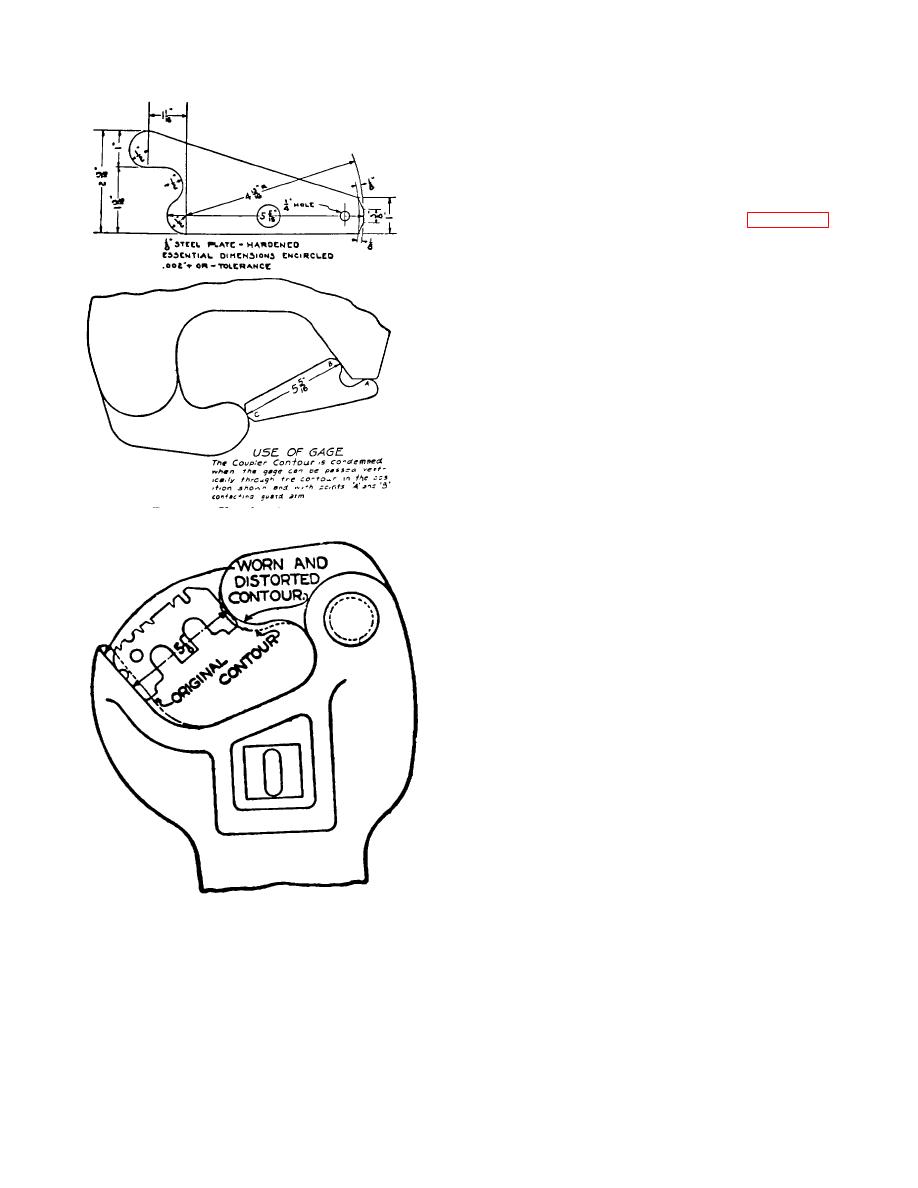
to exceed 5 1/8 inches, as shown in figure 7-4. The
knuckle opening may be exceptionally large.
This
condition may be corrected by building up (by welding)
the knuckle where it makes contact with the lock fulcrum.
However, a new coupler may be installed under these
circumstances. If the excessive opening is due to a worn
knuckle in the knuckle pinhole, replacement of the
knuckle may be required A knuckle worn on the face or
back bearings will be condemned by gagging. Such
knuckles will be replaced. Knuckles are sometimes found
cracked down the face. Such cracks are dangerous, and
the knuckle
should be removed and replaced.
d. Knuckle Pins. Knuckle pins are frequently found
defective. When replaced, pins of the proper size must
be used. Larger pins might crack the pinhole casting, and
smaller or undersized pins will become loose and will
Figure 7-3. Use of contour gage.
create slack, permitting the passing of the knuckle on the
adjoining car between the knuckle and the guard arm.
Cotter keys should not be used in knuckle pins except on
fixed end gondola and hopper cars.
e. Slack. If any slack exists between the coupler butt
and the follower plate or draft gear body, the cause should
be determined and remedial action taken. Slack usually
is caused by a worn coupler butt, but may be due to
defective draft gear (chap 6). Worn coupler butts may be
built up by electric welding or shim plates inserted to
eliminate slack.
common use on Army rolling stock are attached to the
draft gear yoke by draft keys inserted laterally through
holes in the yoke and coupler shank or butt. It is
supported underneath by a coupler carrier (iron) secured
to, or part of the underframe, and a shim or wear plate
between the carrier iron and the shank of the coupler. To
remove the coupler, the following procedure is used
(assembly is in reverse order):
Figure 7-4. Use of worn limit gage.
(1) Disconnect the uncoupling lever from the
proper alinement by shimming the carrier, if its height
coupler lock lifter.
is not at least 1/2 inch in excess of the minimum
dimensions specified above, further adjustments should
(2) Remove knuckle pin and knuckle.
be made at the truck springs, center plates, or journal
boxes.
7-3


 Previous Page
