TM 55-203
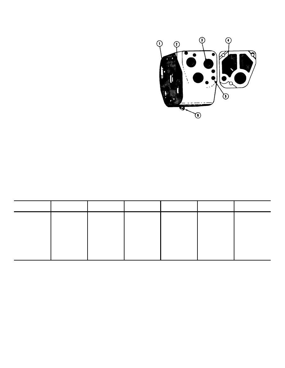
(f) Choke (2), which controls the third stage
of brake cylinder pressure buildup during emergency
application, is located under the emergency portion
cover in the port which bypasses choke (6) when the
timing valve opens. Orifice size 9/64-inch drill.
(2) Springs. The emergency portion contains a
total of nine wire springs which are identified on figure 8-
25 as follows:
(a) Accelerated release check valve spring
5, holds the check valve (4) to its seat.
(b) Spillover check valve spring 6, holds
check valve (8) to its seat.
(c) Diaphragm spring 7, holds the slide
valve to its seat when the diaphragm is balanced.
(d) Vent valve spring 20, holds the
emergency vent valve to its seat.
(e) Inshot check valve spring 25, holds the
check valve in contact with inshot piston stem
Figure 8-24. Location of the six emergency portion
(f) Emergency piston spring 28, resists
choke fittings.
movement of the spring guide in the piston stem.
(g) Return sprang 31, returns the piston and
(j) Spring identification. The following tabulation gives
slide valve to normal release position when brake pipe
the Westinghouse Airbrake data necessary to identify
and quick-action chamber pressures are equalized.
each of the springs described.
(h) Graduating valve spring 34, holds the
graduating valve to its seat on the slide valve.
(i) Inshot piston spring 48 resists inshot
piston movement until brake cylinder pressure rises to
15 pounds.
Table 8-2. Spring Identification AB Emergency Portion
Approximate
Approximate
Approximate
Approximate
Reference No
Part No
0. D.
diameter wire
free height
No turns
Material
5
A94952
3/4"
.072"
1 13/32"
7
Ph Bronze
6
A94581
3 1/64"
.028"
1 3/32"
7
Ph Bronze
7
A94839
11/16"
.064"
1 1/8"
6 1/2
Ph Bronze
20
A81643
1 3/8"
.121"
2 23/32"
71,/2
Steel
25
A94836
33/64"
.050"
1 23/32"
14
Ph Bronze
28
A501006
13/16"
.062"
2 13/32"
11
Steel
31
A500944
1 27/32"
.187" sq.
2 29/64"
6
Steel
84
A93940
5/32"
.020"
21/32"
12
Ph Bronze
48
A95032
1 3/16"
.098"
11/32"
8
Steel
(3) Inspection, lubrication, and assembly of
These lugs engage under a lip around the outer edge of
parts. Inspection, lubrication, and assembly of parts is
the cavities in the body casting. To remove the spring
the same as that of the service portion with the following
and valve, press down on spring retainer and tilt it so
exceptions:
that one lug is exposed upward. When in this position,
(a) The main (emergency) piston cannot be
the parts can be readily removed and can be
removed without first removing the ball check cover and
reassembled by using the same method in reverse.
taking out the slide valve strut which holds the slide
(c) If the vent protector chamfer at the
valve to its seat. Damage will result if force is used to
exhaust of the emergency portion body is pitted
remove the emergency piston from its bushing without
excessively due to rust, refinish the surface with emery
first removing the strut.
cloth or a suitable reamer. Do not remove
(b) The springs behind the vent valve and
the inshot valve are held in place by circular metal
retainers which have lugs on two opposite sides.
8-28


 Previous Page
