TM 55-203
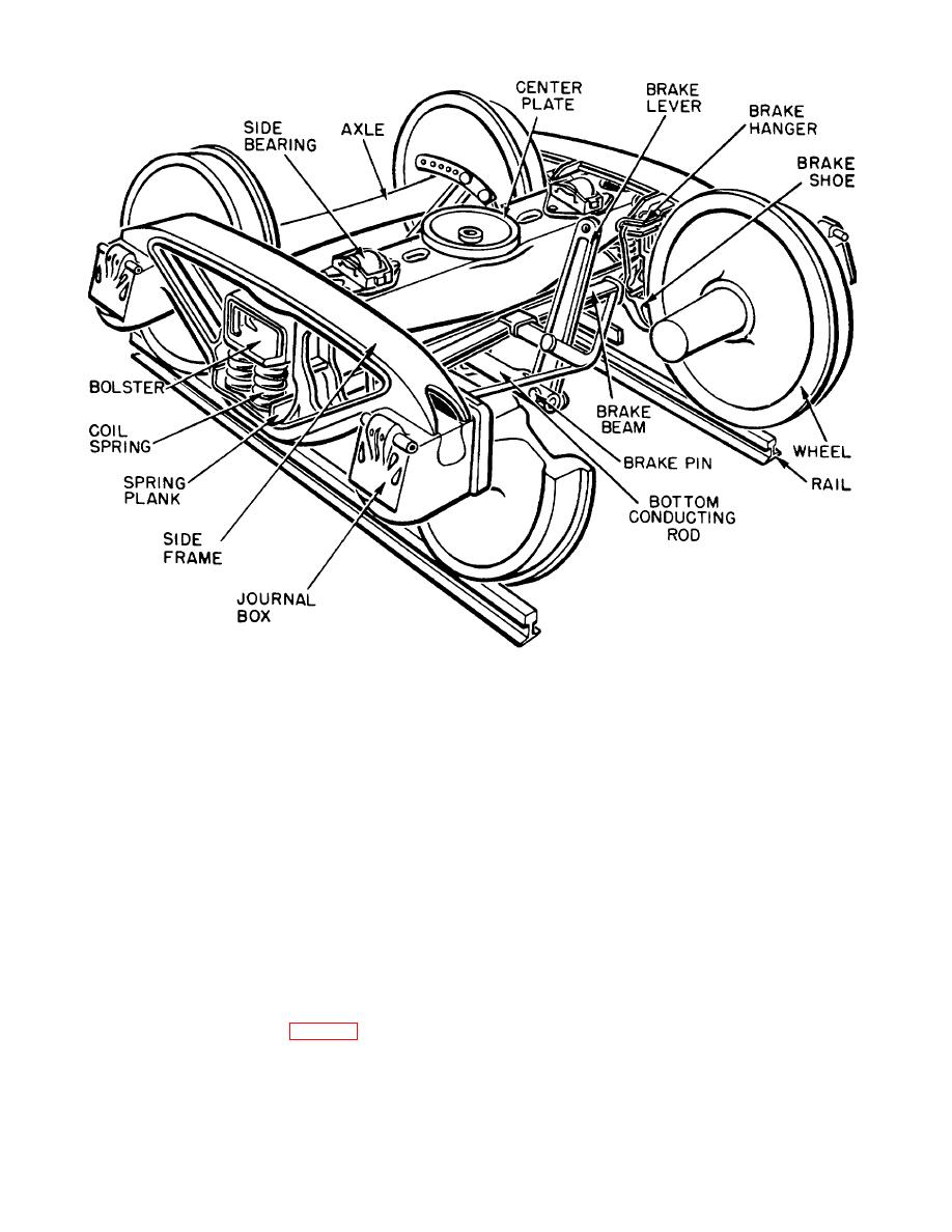
Figure 4-28. Typical truck, assembled.
car's underframe and load. It is set crosswise and the
usually is removed and a new or reconditioned one
matching car body bolster rests on it, secured by the
installed. When it is necessary to build up a !surface by
weight of the car and the matching of the male and
welding, it should be done evenly to produce the desired
female forged or cast-steel center plates. A loose
finish without excessive grinding.
Building up of
center pin in the center plates helps resist lateral
surfaces and the welding of cracks or fractures at any
movement. Under normal conditions, the truck bolster
location are permissible on CONUS-type equipment
oscillates in its position between the columns of the side
provided the side frame is of U-section design,
frame. On application of the brakes, if severe, the
manufactured subsequent to 1926. In CONUS, AAR
Code of Rules governs these repairs Frames must be
bolster will tilt, and the corners of the bolster will rub
removed from the truck, and the section to be welded
against the faces of the truck columns (side frames).
With its fitted ends working in and guided by the cast
must be preheated locally to approximately 6000 F.
columns of the cast-steel truck side frames, the truck
before welding is started. Frames must be normalized
bolster transmits its load to the bottom spring clusters
after welding has been completed and legibly marked
with place and date (AAR regulations in CONUS). On
(leaf springs in passenger cars) which have caps and
certain limited sections of the Journal box and brake
bearing plates. The frame load is in turn transferred to
the axle journals and wheels and then to the rails
hanger bracket, heat treatment is not required.
through journal bearing assemblies (brass and wedge)
4-20. Truck Bolster
or roller bearings located in the journal boxes of the side
frames.
bearing part of the truck. It is designed to support the
4-26


 Previous Page
