CEMP-E
TI 850-02
AFMAN 32-1125(I)
1 MARCH 2000
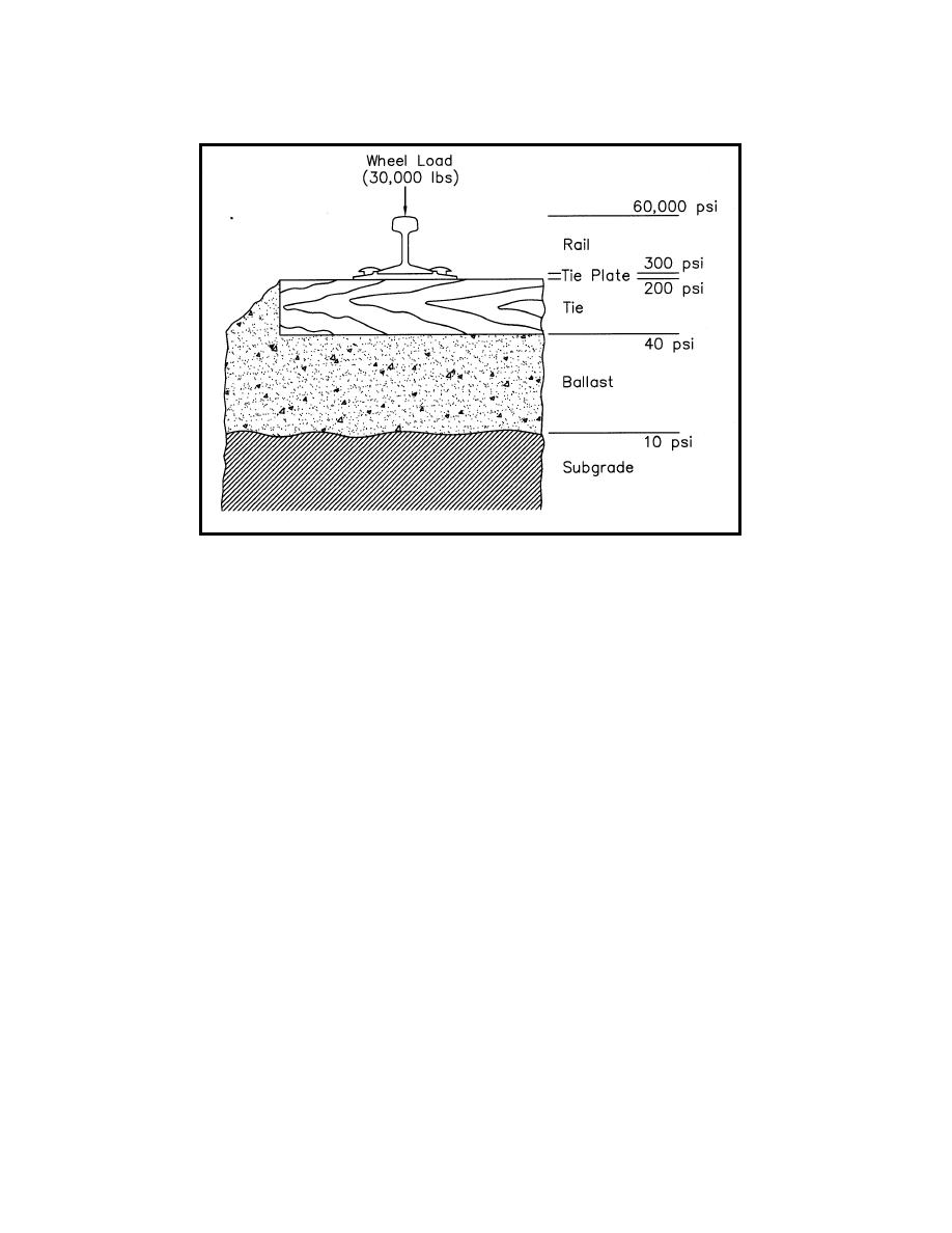
Figure 6-11. Example Vertical Pressure Reduction through the Track
c. Behavior under Load. It is important to note that, while track construction is relatively simple, its
behavior under load is not. An improvement (or increase in strength) in one track component may cause
an increased load on another. It is not uncommon for an improvement (or increase in strength) of one
track component to cause an increased load on another.
6. TRACK DESIGN METHODS.
a. Computer Program Available. A computer program for basic track structure design, called TRACK, is
available through the PCASE Internet Site (http://pavement.wes.army.mil/pcase.html) or the Army
Transportation Systems Center (CENWO-ED-TX). Its use is recommended.
b. Manual Design Procedure. If computer programs are not accessible or if a computer is unavailable,
the design procedure in paragraph 7 may be used as an alternative. A disadvantage of this method,
however, is that very little data exists to correlate the value of track modulus with the properties of
individual rail support components: ties, ballast, and subgrade.
7. AREMA DESIGN PROCEDURE (1995-MODIFIED).
a. Applying the AREMA Method to Military Track.
(1) The AREMA method leaves several choices and judgments open to designers, to be set
according to situation and policy. And like most AREMA criteria, the method is also oriented toward those
commercial lines that carry medium to heavy traffic volumes (more than 10 million gross tons per year)
and operate at medium or higher speeds (more than 40 mph).
6-13


 Previous Page
