CEMP-E
TI 850-02
AFMAN 32-1125(I)
1 MARCH 2000
Table 6-5. Track Center Distances
Minimum Distance
Between
Between Center lines (ft)
Main tracks
15
Siding or yard track and main
15
Yard or storage tracks
14 (15 if space permits)
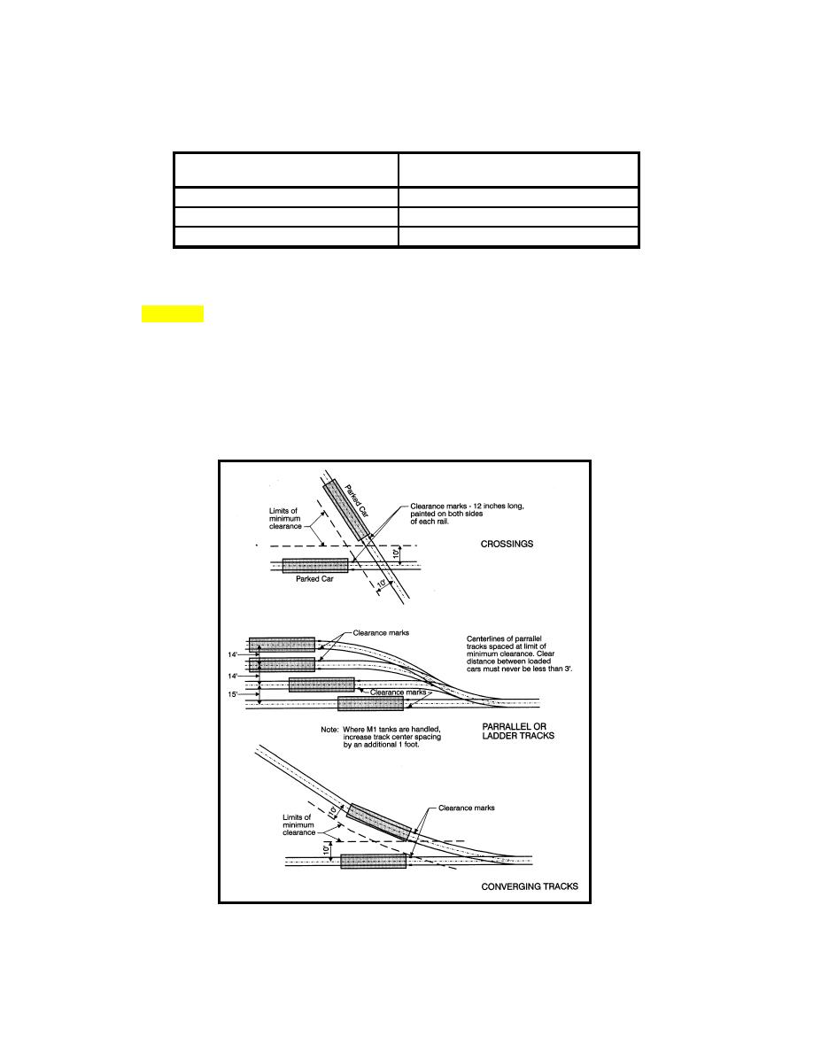
f. Clearance Points at Turnouts, Ladder Tracks, and Crossings.
(1) Figure 6-9 shows how to determine the location of clearance points at turnouts, ladder tracks, and
rail crossings. As no car or piece of equipment may be left standing on a track with any part of it
extending past the clearance point (toward the track junction), the clearance point will determine the
usable length of sidings, loading, yard, and storage tracks.
(2) Clearance points will be marked by a 12-in. yellow bar painted on both sides of the rail base.
(3) If derails are used, they must be set to derail equipment before it reaches the clearance point.
Figure 6-9. Location of Clearance Points
6-11


 Previous Page
