CEMP-E
TI 850-02
AFMAN 32-1125(I)
1 MARCH 2000
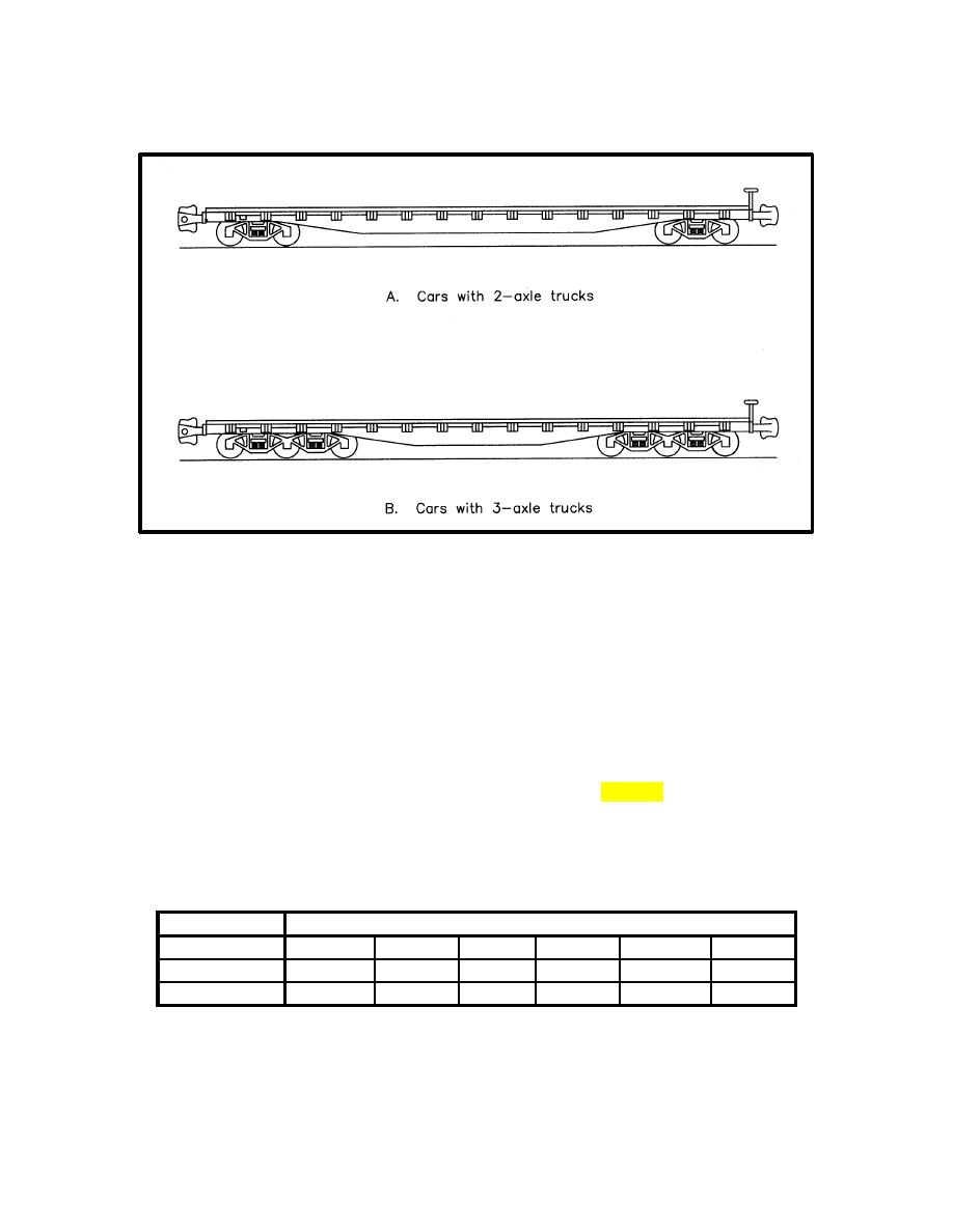
Figure 6-13. Design Wheel Configurations
(3) The track is evaluated assuming that a wheel is centered over a tie, with an adjacent wheel on
either side contributing to the loads, deflections, and stresses as occurs when two cars are coupled
together. Referring to figure 6-13(a), the maximum tie, ballast, and subgrade loads will occur under
wheels one and four (counting from the left), while the maximum rail bending stress will occur at wheels
two and three. For the wheel configuration in figure 6-13(b), the maximum tie, ballast, and subgrade
loads will occur under wheels two and five, while the maximum rail bending stress will occur at wheels
three and four.
(4) The effect of wheels farther than 100 in. from the design wheel is negligible.
d. Select Trial Track Modulus (u). The track modulus values listed in table 6-6 are suggested starting
points for design. In the table, track type "main" refers to main running tracks, while "auxiliary" includes
sidings, wyes, loading, spur, storage, interchange, and light use tracks.
Table 6-6. Suggested Design Track Modulus Values
Design Wheel Load Range (1,000's of pounds)
Track Type
20 - 25
25 - 30
30 - 35
35 - 40
40 - 45
45 - 50
Main
1500
1800
2000
2300
2600
2900
Auxiliary
1200
1300
1500
1700
2000
2200
6-16


 Previous Page
