CEMP-E
TI 850-02
AFMAN 32-1125(I)
1 MARCH 2000
e. Select Rail Size.
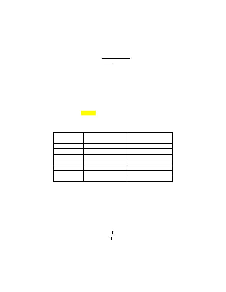
(1) Use equation 6-5 to determine a minimum rail weight:
21200
Wo = 315 -
P
)(α ) + 67
(
1120
Eq 6-5
Wo
=
Weight of rail (lb/yd)
P
=
Design wheel load (lb)
α
=
Impact factor, where:
α
=
1, where design operating speed is 25 mph or less.
α
=
1.4, where design operating speed is more than 25 mph.
(2) Select a rail section from table 6-7 of equal or greater weight than calculated above.
Table 6-7. Rail Sections
Moment of Inertia:
Section Modulus to
4
Base: Zb (inches3)
Rail Section
I (inches )
100 ARA-B
41.3
15.7
112 RE
65.5
21.8
115 RE
65.6
22.0
130 RE
77.4
25.5
132 RE
88.2
27.6
133 RE
86.0
27.0
136 RE
95.4
28.4
f. Determine Moment and Loading Coefficients.
(1) The moment and loading coefficients account for the affects of wheels adjacent to the design
wheel. Adjacent wheels reduce rail moment and increase tie, ballast, and subgrade load.
(2) Calculate X1 using equation 6-6. (X1 should normally range between 28 and 40):
I
x1 = 82
4
u
Eq 6-6
X1 =
Distance from design wheel load to point of zero bending moment (inches).
Vertical moment of inertia of rail section (in.4).
I=
u=
Stiffness of rail support, or track modulus (psi).
6-17


 Previous Page
