TM 55-203
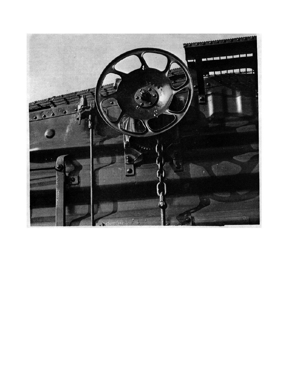
Figure 8-6. Vertical geared-type handbrake, 50-ton USA boxcar, showing retainer valve.
the braking force beneath the car. When the straight
to a bracket on the underframe, and the horizontal brake
shaft is used, it will rotate as the handwheel is turned.
chain fastened to the end of the vertical shaft. A gear
When the chain is used, it will rise upon brake
and pawl, usually near the top of the vertical shaft,
application and wind on a small shaft or drum or it will
prevent the equipment from backing off. When the
lower upon brake release, thus unwinding. When the
hand- wheel is turned to apply the brakes, the shaft and
braking force reaches a point below the level of the
the gear turn, and the pawl engages each tooth of the
underframe, it must change direction to connect to the
gear, preventing backing off.
Simultaneously, the
foundation brake rigging levers and rods and thus
horizontal brake chain winds around the turning shaft
operate the brakeshoes.
and applies the brakes. To release the brakes, the pawl
should be disengaged and the handwheel turned in the
opposite direction to permit the chain to unwind from the
8-5.
Design
vertical shaft. A variation of the straight-shaft type,
embodying the same principle as the gear type, is to
a. Early Straight-Shaft Design. The straightshaft
have the end of the shaft anchored to the under-
design consists of a handwheel or hand lever, a shaft
running vertically along the end of the car and anchored
8-7


 Previous Page
