c. A head-contact joint bar bears against the underside of the rail head. The arrows in
figure 3.19C indicate the points of contact in a typical assembly.
3.27. SUPPORT AND LOCATION
How a rail joint is supported and located relative to its opposite number on the other rail
vary among roads. A rail joint may be supported by one tie, suspended between two ties, or
supported by three ties. On some lines, a rail joint is placed opposite one on the other rail or
opposite the center of the other rail. These varying practices are examined in the subparagraphs
following.
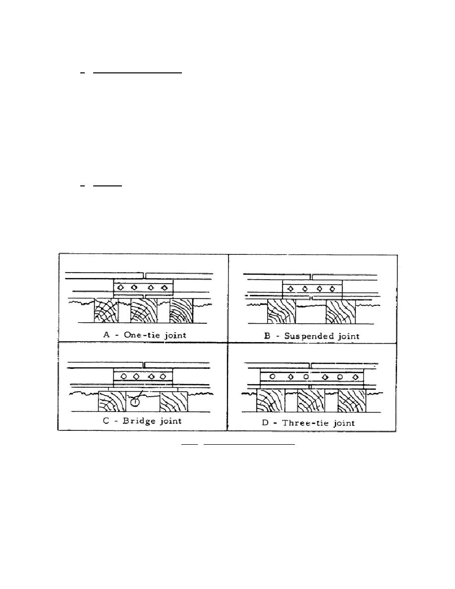
a. Support. Any one of three methods of supporting a rail joint may be used. A joint
may be supported by one tie, suspended between two ties, or supported by three ties.
(1) One tie. Having the ends of the two rails to be spliced on one tie is called a
supported joint. This form of joint is particularly suitable for lightweight rails. See figure
3.20A.
Figure 3.20. Methods of Joint Support.
(2) Two ties. In a suspended joint, the rail ends meet between a pair of ties, as figure
3.20B shows. The two ties in question are laid closer together than usual. Often a base or bridge
plate extending from one tie to the other carries the rail ends. When
65


 Previous Page
