of the switch rails away from the points. Switch plates are used until the turnout and main-line rails have
diverged far enough to permit use of separate tie plates.
2.10.
SWITCH TIES
The entire turnout is supported on switch
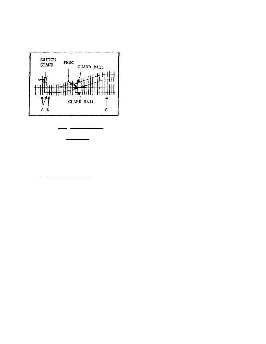
ties. Look now at figure 2.14. Notice at point A that
the two ties supporting the switch points also
support the switch-throwing mechanism. They are
referred to as headblock timbers and are 15 feet
long. The succeeding ties, the actual switch ties,
gradually become longer toward the frog end of the
turnout, as shown in figure 2.14 between points B
and C. For a No. 8 turnout, for example, tie lengths
vary from 8 1/2 feet just beyond the switch points to
15 1/2 feet beyond the heel of the frog.
Figure 2.14. Arrangement and
Location of
Switch Ties.
2.11.
SWITCH-THROWING MECHANISM
Several references to the switch-throwing mechanism are made in earlier paragraphs. Just what is it?
What does it do?
a. What the mechanism is. The switch-throwing mechanism consists essentially of a switch stand with a
throw lever and a connecting rod. The switch stand is located on two 15-foot headblock timbers, shown at A in
figure 2.14 opposite the switch points and usually on the right side of the track with respect to the normal
direction of traffic. The center of the stand is approximately 6 feet 6 inches from the centerline of the track. The
mechanism may be operated manually or electrically. Hand-thrown switches are thrown by the operators of small
stations, yard switchmen, or traincrews. Electrically powered switches are thrown by remote control by operators
stationed at towers or interlocking plants.
A typical manually operated switch stand is shown in figure 2.15. The targets (1) are painted panels to
show the direction or the track for which the switch is lined--green, switch normal or set for main-line operation;
red, switch reversed or set for turnout.
42


 Previous Page
