for combustion; and an emergency fuel cutoff valve to stop fuel from flowing from the tank in an
emergency.
Generally speaking, fuel begins to enter the combustion space of the cylinder when the piston is
about 15 degrees before top dead center. When the kindling-combustion temperature of the fuel is
reached, the sprayed droplets of fuel begin to burn. The fuel still being injected then burns as soon as it
leaves the injection nozzle. When fuel is delivered by the injection pump under sufficient pressure, the
nozzle valve lifts against spring pressure; fuel enters the nozzle and is sprayed from it into the
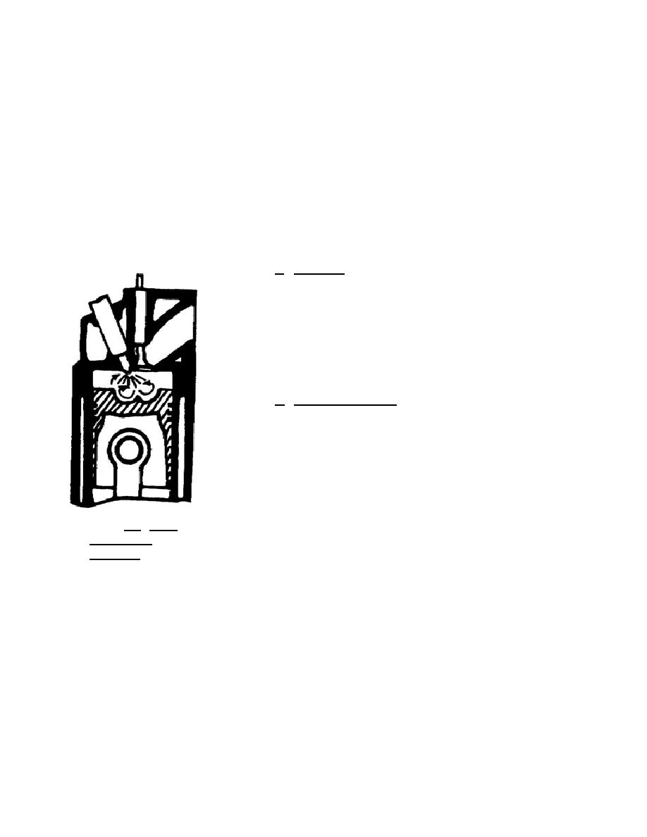
combustion chamber. Several types of combustion chambers are used. The simplest type, and the one
most commonly used in military diesel-electric locomotives, is the direct or open chamber, illustrated in
figure 1.6. The entire supply of air is in the cylinder, with a depression in the piston crown providing
the combustion space. With this type of combustion chamber, heat loss is small and fuel consumption
low. Also, the engine can start quickly during cold weather.
a. Fuel tank. The fuel is contained in a tank fitted with
baffle plates to prevent surging and with a pit to catch sludge and
water so that they can be drained out. Since the fuel pumps alone
cannot raise the fuel to the cylinder's intake port, two alternative
methods of supplying fuel can be used. A small service tank can
be located above the pumps and the fuel can enter the pumps by
gravity or, if the service tank is not used, fuel can be pumped from
the main tank by a mechanical or electric pump.
b. Fuel injection pump. A fuel injection pump, illustrated in
figure 1.7, not only creates the injection pressure but determines
the amount of fuel injected. Its toothed rack, controlled by the
engine governor or by the speed control lever, varies the amount of
fuel and actuates all the pump elements. The pump is primarily a
piston or plunger, sliding in a barrel. The lower end of the plunger
has two projections which engage slots in the control sleeve. Oil
enters the intake port and is trapped above the helical groove and
slot whenever it rises to cover the spill port. Various positions of
Figure 1.6. Open
the groove and slot are shown in figure 1.8. Position (a) shows the
Combustion
plunger at its lowest point and position (b) shows it when both
Chamber.
ports are closed during its rise in the cylinder. Positions (c), (d),
and (e) show the plunger when the locomotive
10


 Previous Page
