may or may not end where it started, electricity won't start unless it has a complete circuit back to its
source, a generator or battery.
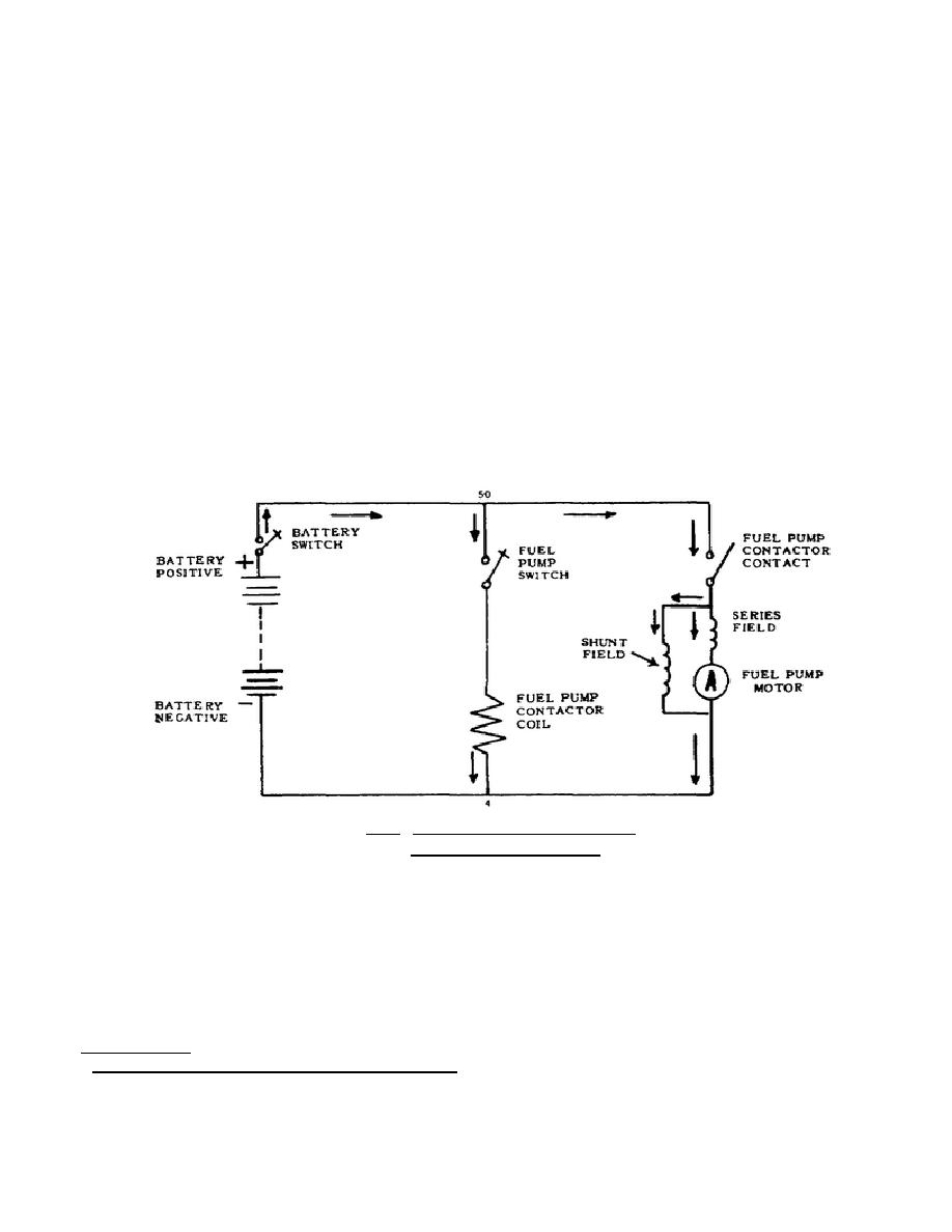
Look at the schematic diagram of the fuel pump circuit in figure 1.12 and trace out one of the
highways on the electrical map. Here you see a battery, a fuel pump contactor coil, its contacts, and a
fuel pump motor. The symbol (A) is standard for motor armature. All switches and contacts are shown
on their normal position, that is, with no power on.
The job of the fuel pump is to pull the fuel out of the tank and deliver it to the engine. It
"shovels the coal" to the engine. The first step in starting this pump is to close the battery knife switch.
This connects the battery positive to the 50 wire. But though the 50 wire is now "hot," nothing will
happen because there is no path from it to the 4 wire, or battery negative. So next, close the fuel pump
switch and make such a path. The current can now flow from the 50 wire through this switch and the
fuel pump contactor coil to the 4 wire. When current flows through the coil, it sets up a magnetic field
and closes the contactor. Now there is a path from the 50 wire down through the fields and armature of
the fuel pump motor to the 4 wire. Current flowing through this path starts the motor; this drives the
pump and furnishes fuel to the engine.
Figure 1.12. Schematic Wiring Diagram --
Fuel Pump Motor Circuit. *
In the simple diagram in figure 1.12, parts of the circuit are identified by their names as well as
by symbols. Oftener than not,
*Diesel-Electrics . . . How to Keep 'Em Rolling, Simmons-Boardman Publishing Corp, pp. 75-76.
24


 Previous Page
