CEMP-E
TI 850-02
AFMAN 32-1125(I)
1 MARCH 2000
d. Cooper E Series Loading.
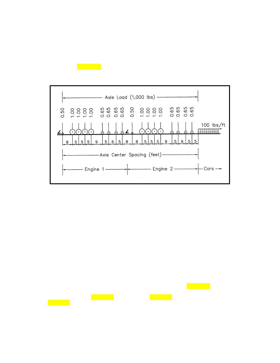
(1) The design live load is expressed using the Cooper E series loading configuration adopted by the
AREMA about 1905. Figure 7-19 illustrates a unit E1 axle loading. Higher loadings are obtained by
multiplying each load by the same constant; wheel spacings do not change. Thus, an E60 loading would
show the largest axle loads as 60,000 lb.
Figure 7-19. Cooper Load Configuration for Bridges
(2) To allow an easy comparison of permissible in-service loading (or rating) over the life of a bridge
with the loads used in their original design, and to compare the effect of different engine and car loads for
either design or rating, the railroad industry kept the basic Cooper load configuration and used it to
represent all bridge loadings and bridge capacity ratings.
e. Equivalent Cooper Loading.
(1) In use, the loading from a train of typical (or heaviest common) cars (the design train) is converted
to the Cooper E loading that would have the same effect on the bridge.
(2) For a given design train, the equivalent Cooper loading (E value) will vary with train operating
speed, bridge span length, and bridge design.
(3) As the actual load distribution from current trains will differ from the Cooper configuration, the
equivalent Cooper loading will not be a constant for all bridge components. Figure 7-20 shows the
relationship between equivalent Cooper loading (at 60 mph) and span length for one type of steel bridge
and for the loading shown in figure 7-21. As an example, figure 7-20 indicates that, for a 60-ft span, the
train in figure 7-21 produces an effect equivalent to a Cooper E48 load with respect to floor beam
reaction, an E57 load with respect to end shear, and an E60 load with respect to bending moment.
7-23


 Previous Page
